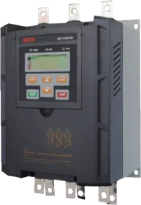
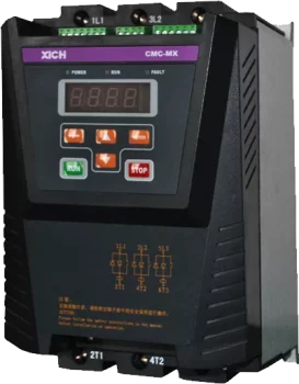
Key Features of the CMC-MX Modbus RTU Soft Starter with Built-in Bypass
Internal bypass contactor and current transformer — nothing external to wire
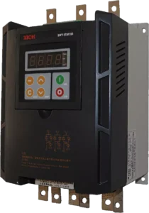
The CMC-MX is a Modbus RTU soft starter for 3-phase 380 V … integrated inside the enclosure. When the motor reaches full speed the internal bypass contactor closes and the thyristors are taken out of circuit, so the starter does not need an external bypass contactor, external CTs, or the panel space and wiring that come with them. For panel builders who standardise on low voltage soft starters for general industrial loads, this is the difference between a two-component starting section and a single device: fewer terminals, shorter busbars, less heat inside the cabinet and a shorter assembly time.
Current limiting start, voltage ramp start and programmable kick start
Two starting modes are available and a programmable step (kick) start can be applied in either of them, so the starting curve can be matched to the load instead of the other way round:
- Current limiting soft start — the output voltage rises until the output current reaches the set limit (parameter C005, 150–500 % of motor rated current, factory 350 %). The current is then held at that value while the motor accelerates and the voltage is raised to full value. This is the mode to use where the supply capacity is limited or the network must not see a heavy inrush.
- Voltage ramp start — the voltage rises from the initial value (C003, 25–100 % Ue, factory 30 %) to full voltage over the ramp time (C004, 0–60 s, factory 10 s). It is intended for high-inertia loads, where it reduces the starting impact and the mechanical stress on the drive train.
- Step torque (kick) start — an instantaneous high starting torque is applied for a settable step time (C001 step voltage, C002 step time) to overcome large static friction, after which the motor continues on the normal initial-voltage-and-ramp curve. Loads such as crushers, mixers and screw compressors need this kick to break away.
Free stop and soft stop
With the soft stop time (C007) set to zero the starter stops in free stop mode: the bypass contactor control relay is blocked and the thyristor output is blocked immediately, so the motor coasts down on the inertia of the load. With a soft stop time set, the starter disconnects the bypass contactor first and then reduces the output voltage to the soft stop termination voltage (C008, 25–60 %) within the soft stop time before switching to free stop — the mode to use wherever the driven machine has to be brought down under control rather than by inertia.
Motor protection with a selectable electronic overload curve
Both the motor and the starter are protected against the faults that actually occur in service:
- phase failure (input and output)
- overcurrent and overcurrent duration (C101, C102)
- short circuit and thyristor (SCR) protection
- overheat protection
- phase current imbalance and its delay time (C103, C104)
- leakage detection
- electronic thermal overload with a selectable trip curve — 10A, 15, 20, 25 or 30 level (C105)
- internal contactor fault
- underload protection, which can be switched off by setting C111 to 100
The motor rated current is entered in C100, and it must not be set below 50 % of the rated current of the controller. When a protection operates, the corresponding fault type is shown on the display for fast diagnosis, and the last seven faults are kept in the parameters C310 to C316.
Modbus-RTU over RS485 — up to 32 starters on one bus
The CMC-MX has an RS485 port with Modbus-RTU protocol. Up to 32 units can be connected on one network, with communication addresses from 1 to 32 (factory default 1) and baud rates of 2400, 4800, 9600 or 19200 bps (factory default 9600). Start, stop, parameter read and write and status monitoring are all available over the bus, and standard Modbus frames with CRC checking are used, so the starter can be dropped into an existing PLC or SCADA network without a gateway. The full register map is listed further down this page.
4–20 mA analog output
An analog output (terminals X1/1 AO− and X1/2 AO+) delivers 4–20 mA into a load of 150–500 ohm for remote indication. Parameter C208 selects average current 1 (0–200 % Ie) or average current 2 (0–400 % Ie), so the signal can be scaled to the range the control system expects.
50 / 60 Hz selected by parameter
The power frequency is set in the parameters, so the same CMC-MX covers 50 Hz and 60 Hz networks. For an export project the destination grid does not change the part number, and a machine built for one market can be re-used in another with a setting change.
4-digit display, keypad and fault memory
A 4-digit LED display with a keypad monitors the working condition of the equipment and gives rapid fault diagnosis on site. Setup is done from the same keypad, with parameters grouped into start and stop control (C000–C016), motor protection (C100–C116), port setting (C200–C216) and recording (C300–C316).
Technical Specifications
| Applicable motor | Ordinary squirrel cage AC asynchronous (induction) motor |
|---|---|
| Power range | 7.5 – 280 kW |
| Rated current | 18 – 560 A, 18 ratings in total |
| Mains voltage, standard wiring | 3-phase AC 380 V ±15 % |
| Mains voltage, internal delta wiring | 3-phase AC 380 V ±30 % |
| Control supply | AC 110 – 220 V ±15 %, 50 / 60 Hz |
| Start ramp mode | Current limiting start, voltage ramp start, programmable step (kick) start |
| Stop mode | Free stop, soft stop |
| Current limiting factor | 150 – 500 % Ie (factory 350 %) |
| Initial voltage | 25 – 100 % Ue (factory 30 %) |
| Ramp time | 0 – 60 s (factory 10 s) |
| Soft stop time | 0 – 60 s |
| Soft stop termination voltage | 25 – 60 % (factory 25 %) |
| Starting frequency | Frequent or infrequent starts; no more than 10 starts per hour recommended |
| Logic input | Impedance 1.8 kohm, power supply +24 V |
| Analog output | 4 – 20 mA, load impedance 150 – 500 ohm |
| Protection functions | Phase failure, overcurrent, short circuit, SCR (thyristor) protection, overheat, phase current imbalance, leakage detection, electronic thermal overload, internal contactor fault, underload, wiring and inner fault |
| Electronic overload curve | Selectable 10A / 15 / 20 / 25 / 30 level |
| Communication | Modbus-RTU, RS485; up to 32 units; 2400 – 19200 bps |
| Setting and display | 4-digit LED display with keypad; 7 historical faults stored (C310 – C316) |
| Degree of protection | IP00, IP20 |
| Cooling | Natural cooling or forced air cooling |
| Installation | Wall mounted, vertical installation |
| Standard | GB/T 14048.6-2016 |
| Ambient conditions | Altitude up to 2 000 m without derating, above 2 000 m derate for use; ambient temperature −25 to +45 °C; relative humidity below 95 % (20 ± 5 °C); indoor installation with good ventilation, free of flammable, explosive or corrosive gas and conductive dust; vibration below 0.5 G |
Standard wiring means the motor winding is connected in delta or star and the thyristors sit between the supply and the motor. In internal delta wiring the thyristors sit in series with each motor winding, so the current through the starter is 1/1.732 (about 58 %) of the line current — see the internal delta section below.
Model Selection: 18 Models from 7.5 kW to 280 kW
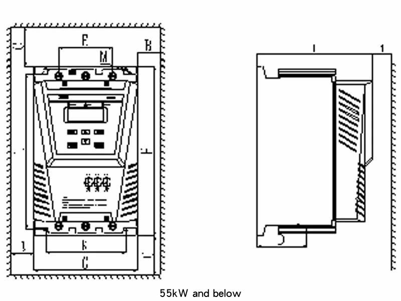
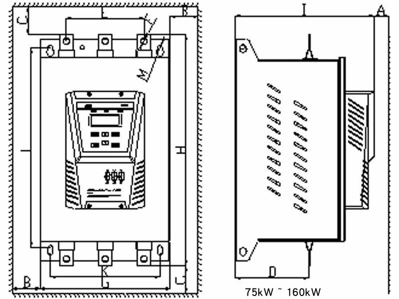
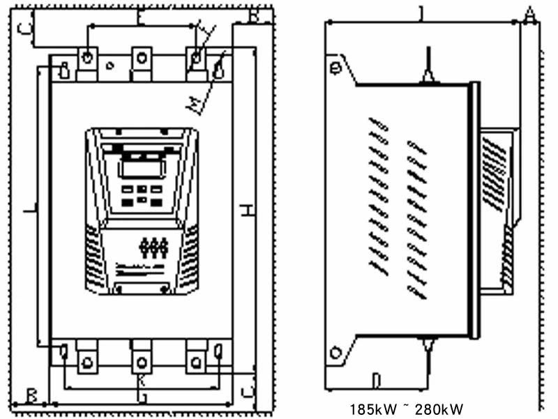
| Model | Rated current | Motor power | Recommended cable, standard wiring | Size W x H x T (mm) | Net weight |
|---|---|---|---|---|---|
| CMC-008/3-MX | 18 A | 7.5 kW | 6 mm² copper | 173 x 275 x 192 | 5.6 kg |
| CMC-011/3-MX | 24 A | 11 kW | 10 mm² copper | ||
| CMC-015/3-MX | 30 A | 15 kW | 16 mm² copper | ||
| CMC-018/3-MX | 39 A | 18.5 kW | 16 mm² copper | ||
| CMC-022/3-MX | 45 A | 22 kW | 16 mm² copper | ||
| CMC-030/3-MX | 60 A | 30 kW | 25 mm² copper | ||
| CMC-037/3-MX | 76 A | 37 kW | 25 mm² copper | ||
| CMC-045/3-MX | 90 A | 45 kW | 35 mm² copper | ||
| CMC-055/3-MX | 110 A | 55 kW | 50 mm² copper | ||
| CMC-075/3-MX | 150 A | 75 kW | 70 mm² copper | ||
| CMC-090/3-MX | 180 A | 90 kW | 20 x 3 copper bar | 285 x 450 x 305 | 25.1 kg |
| CMC-110/3-MX | 218 A | 110 kW | 20 x 3 copper bar | ||
| CMC-132/3-MX | 260 A | 132 kW | 25 x 3 copper bar | ||
| CMC-160/3-MX | 320 A | 160 kW | 30 x 3 copper bar | ||
| CMC-185/3-MX | 370 A | 185 kW | 30 x 4 copper bar | ||
| CMC-220/3-MX | 440 A | 220 kW | 40 x 5 copper bar | 320 x 523 x 330 | 34.5 kg |
| CMC-250/3-MX | 500 A | 250 kW | 40 x 5 copper bar | ||
| CMC-280/3-MX | 560 A | 280 kW | Ask us for the internal delta cable schedule |
Model code: CMC-★★★/3-MX — ★★★ is the applicable motor power code, 3 is the mains voltage class (380 V) and MX is the built-in bypass series. Cable sizes are the standard wiring values from the CMC-MX manual for 380 V; cable size and breaker rating should always be checked against the actual motor current, cable length, installation method and local code.
Motors larger than 280 kW are covered by the CMC-LX built-in bypass soft starter series (7.5 – 630 kW), which uses the same internal bypass concept in a larger frame and is compared with the CMC-MX further down this page.
Internal Delta (Inside-Delta) Wiring
What changes with inside-delta wiring
In standard wiring the thyristors of the soft starter are connected between the supply and the motor, and they carry the full line current. In internal delta wiring the motor winding is connected in delta and the thyristors are placed in series with each winding, so the current that flows through the starter — and through each winding — is 1/1.732 of the line current, about 58 %. The main advantage of the internal triangular control is that the soft starter can be derated: a smaller rating can be selected for the same motor, which reduces both cost and panel size. The mains voltage tolerance in this mode is AC 380 V ±30 %.
When to use it
Internal delta wiring is worth considering for high-power, high-inertia drives where the starting current is the constraint and the cost of the starter is a large part of the panel, and where the motor has six terminals available for delta connection. Standard wiring remains the simpler choice for small motors and for retrofits where the existing motor is already star-connected or has only three terminals brought out. Tell us the motor nameplate data, the starting duty and the wiring method, and we will confirm the correct model and cable schedule.
Terminal Description
| Terminal | Name | Description |
|---|---|---|
| 1L1, 3L2, 5L3 | AC power input | Connected to the three-phase AC power supply (main circuit) |
| 2T1, 4T2, 6T3 | Soft start output | Connected to the three-phase asynchronous motor (main circuit) |
| X1/1 | Analog output AO− | 4 – 20 mA |
| X1/2 | Analog output AO+ | Output load impedance 150 – 500 ohm |
| X1/3 | COM | Common port |
| X1/4 | External control start (RUN) | Start when X1/4 and X1/3 are short-circuited |
| X1/5 | External control stop (STOP) | Stop when X1/5 and X1/3 are disconnected |
| X1/6 | Programmable digital port D1 | Fault clear input or emergency stop input, selected by C201 |
| X2/1 | RS485 ground (GND) | RS485 communication, GND single point grounding |
| X2/2 | RS485+ (A) | Modbus-RTU communication |
| X2/3 | RS485− (B) | Modbus-RTU communication |
| X3/1, X3/2 | Interlocking control relay K1 | Passive normally open, AC 250 V / 5 A, DC 30 V / 5 A |
| X3/3, X3/4 | Fault output relay K2 | Passive normally open, AC 250 V / 5 A, DC 30 V / 5 A; operates in case of fault |
| X3/5, X3/6 | Programmable output relay K3 | Passive normally open AC 250 V / 5 A, DC 30 V / 5 A; function defined by C202 |
| X3/7 | PE | Protective earth |
| X3/8, X3/9 | Control power supply L / N | AC 110 V – AC 220 V ±15 %, 50 / 60 Hz |
For the basic single-node passive control scheme the start and stop contacts are wired to X1/4, X1/5 and X1/3. A passive double-node scheme is also possible, in which RUN and STOP are inching signals; in that scheme the start and stop commands are also valid from the panel.
Key Setting Parameters
| Parameter | Name | Setting range | Factory value |
|---|---|---|---|
| C000 | Starting mode / start ramp mode | 0 – 1 | 0 |
| C001 | Step voltage | 25 – 100 % Ue | 20 % |
| C002 | Step time | 0 – 200 x 10 ms | 0 |
| C003 | Initial voltage | 25 – 100 % Ue | 30 % |
| C004 | Ramp time | 0 – 60 s | 10 s |
| C005 | Current limiting factor | 150 – 500 % Ie | 350 % |
| C007 | Soft stop time | 0 – 60 s | 0 |
| C008 | Soft stop termination voltage | 25 – 60 % | 25 % |
| C200 | Selection of control | 0 keyboard, 1 communication, 2 keyboard and communication | 0 |
| C201 | D1 port input mode | 0 fault clear input, 1 emergency stop input | 0 |
| C202 | Programmable relay output mode | 0 full voltage output, 1 starting process, 2 soft stop process, 3 fault output | 1 |
| C203 | Relay output delay | 0 – 250 s | 0 |
| C204 | Communication address | 1 – 32 | 1 |
| C205 | Communication baud rate | 2400 / 4800 / 9600 / 19200 bps | 9600 |
| C208 | Analog output mode | 0 average current 1 (0 – 200 % Ie), 1 average current 2 (0 – 400 % Ie) | 0 |
Motor protection is set in the C100 group: C100 motor rated current, C101 overcurrent protection value, C102 overcurrent duration, C103 phase current imbalance, C104 imbalance delay, C105 electronic thermal overload level and tripping time, C106 SCR protection option, C107 phase sequence detection, C111 and C112 underload protection. C111 set to 100 disables the underload function.
Modbus-RTU Communication and Register Map
The CMC-MX uses Modbus-RTU over RS485. Up to 32 starters can share one bus with addresses 1 to 32 (factory 1), and the baud rate is set in C205 to 2400, 4800, 9600 or 19200 bps (factory 9600). Transmission uses the standard RTU frame with a silent interval of at least 3.5 characters between frames: slave address, function code, data and a CRC check word, each byte sent as two hexadecimal characters. The registers below are all 16-bit unsigned integers and are readable and writable.
| Register (dec) | Function | Type | Access |
|---|---|---|---|
| 0000 | Starting mode | Uint | R / W |
| 0001 | Step voltage | Uint | R / W |
| 0002 | Step time | Uint | R / W |
| 0003 | Initial voltage | Uint | R / W |
| 0004 | Ramp time | Uint | R / W |
| 0005 | Current limiting factor | Uint | R / W |
| 0006 | Second starting allowed | Uint | R / W |
| 0007 | Soft stop time | Uint | R / W |
| 0008 | Soft stop termination voltage | Uint | R / W |
| 0009 | Starting time delay | Uint | R / W |
| 0010 | Secondary current limiting factor | Uint | R / W |
| 0017 | Motor rated current | Uint | R / W |
| 0018 | Overcurrent protection | Uint | R / W |
| 0019 | Overcurrent duration | Uint | R / W |
| 0020 | Phase current imbalance | Uint | R / W |
| 0021 | Phase current imbalance delay | Uint | R / W |
| 0022 | Electronic thermal overload | Uint | R / W |
| 0023 | SCR protection option | Uint | R / W |
| 0024 | Phase sequence detection | Uint | R / W |
| 0025 | Frequency protection setting | Uint | R / W |
| 0026 | Starting time limit | Uint | R / W |
| 0027 | Motor wiring setting | Uint | R / W |
| 0028 | Current underload setting during operation | Uint | R / W |
| 0029 | Current underload delay output time | Uint | R / W |
| 0034 | Selection of control | Uint | R / W |
| 0035 | D1 port input mode | Uint | R / W |
| 0036 | Relay output mode | Uint | R / W |
| 0037 | Relay output delay | Uint | R / W |
Typical Applications and Recommended Settings
The CMC-MX is used on the general industrial loads that make up most soft starter demand: pumps, fans, compressors, conveyors, mixers, crushers, hoists and escalators. The table below gives the starting settings recommended by the manufacturer for the most common load types, as a starting point for commissioning.
| Load type | Initial voltage (%) | Start ramp time (s) | Stop ramp time (s) | Current limit ILIM |
|---|---|---|---|---|
| Foreship propeller | 25 | 10 | 0 | 2.5 |
| Centrifugal fan | 25 | 20 | 0 | 3.5 |
| Centrifugal pump | 25 | 6 | 6 | 3 |
| Piston compressor | 25 | 15 | 0 | 3 |
| Hoisting machinery | 30 | 15 | 6 | 3.5 |
| Mixer | 40 | 15 | 0 | 3.5 |
| Crusher | 30 | 15 | 6 | 3.5 |
| Screw compressor | 20 | 15 | 0 | 3.5 |
| Spiral conveyor belt | 25 | 10 | 6 | 3.5 |
| No-load motor | 25 | 10 | 0 | 2.5 |
| Conveyor belt | 25 | 15 | 10 | 3.5 |
| Heat pump | 25 | 15 | 6 | 3 |
| Escalator | 25 | 10 | 0 | 3 |
| Air pump | 25 | 10 | 0 | 2.5 |
Recommended settings from the CMC-MX manual, for reference only. ILIM is the current limiting factor, the same quantity that is set in C005 (150–500 % Ie). Final settings should be confirmed on site during commissioning, with the actual load, supply and starting duty.
CMC-MX, CMC-LX or CMC-HX — Which Series Fits Your Motor
Brigoind supplies the three XICHI low voltage soft starter families that cover most industrial starting duties, so the right frame can be chosen without changing supplier:
- Built-in bypass soft starter (CMC-LX, 7.5–630 kW) — built-in bypass contactor and current transformer in a larger frame, for motors above the CMC-MX range and for projects that want one series across a whole plant.
- CMC-HX series, up to 710 kW — the high power option for large pumps, fans, compressors and crushers.
- CMC-MX series, 7.5 – 280 kW — this page. The most compact and economical of the three, for machines and panels where space is tight.
If you are not sure which series matches your motor, send us the motor nameplate (power, current, voltage, speed), the load type and the starting duty, and we will size it for you. A wider overview of the drive range is on our industrial drives overview page.
FAQ
Does the CMC-MX need an external bypass contactor or current transformer?
No. Both are built into the enclosure, so the starting section only needs the soft starter itself plus a breaker or fuses on the supply side. This is the main difference from a standard soft starter, and it is why a CMC-MX panel is smaller, cooler and faster to wire.
Should I use current limiting start or voltage ramp start?
Use current limiting start where the supply capacity is limited or the network must not see a heavy inrush: the current is held at the set limit (factory 350 % Ie) while the motor accelerates. Use voltage ramp start for high-inertia loads, where the smooth voltage rise matters more than the current ceiling. A programmable kick start can be added to either mode for loads with a high breakaway torque, such as crushers, mixers and screw compressors.
What protections are included?
Phase failure, overcurrent and overcurrent duration, short circuit and thyristor (SCR) protection, overheat, phase current imbalance, leakage detection, electronic thermal overload with a selectable 10A / 15 / 20 / 25 / 30 trip curve, internal contactor fault and underload protection, which can be disabled by setting C111 to 100. The last seven faults are stored in the parameters C310 to C316 for later reading.
How many CMC-MX units can be connected on one RS485 network?
Up to 32. Communication addresses run from 1 to 32 (factory default 1) and the baud rate is set to 2400, 4800, 9600 or 19200 bps (factory default 9600). Standard Modbus-RTU frames with CRC checking are used, so the starter connects directly to a PLC or SCADA system.
Is the CMC-MX a 50 Hz or a 60 Hz product?
Both. The power frequency is selected by parameter, so the same unit works on 50 Hz and 60 Hz networks. For export projects this means the destination grid does not change the part number.
What cable size do I need?
For standard wiring from the 7.5 kW model upwards the recommended primary conductor is 6 mm² copper, rising through 16 mm² at 15 kW, 25 mm² at 30 kW, 50 mm² at 55 kW and 70 mm² at 75 kW, after which copper bar is used — from 20 x 3 at 90 kW to 40 x 5 at 250 kW. The full list is in the model selection table above. With internal delta wiring the current through the starter is only about 58 % of the line current, so the cable and the starter rating can usually be reduced; ask us for the schedule for your motor.
Can I use the CMC-MX above 280 kW?
No. The CMC-MX covers 7.5 – 280 kW (18 – 560 A) in 18 models. Above that, step up to the CMC-LX series (7.5 – 630 kW), which uses the same internal bypass arrangement, or to the CMC-HX series for the largest motors. The series comparison above tells you which one matches your motor.
What is supplied with each starter?
Every unit is shipped with the user manual, the product qualification certificate and the standard mounting parts. Dimensional drawings, the terminal diagram and the parameter list are available on request in English, and we can prepare a cable and breaker schedule for your specific motor and wiring method on request.
Request a Quotation
Send us the motor power, rated current, supply voltage and the load type, and tell us whether you will use standard wiring or internal delta wiring. We will come back with the right CMC-MX model (or the CMC-LX / CMC-HX alternative if your motor is outside the CMC-MX range), a cable and breaker recommendation, and a written quotation.
As a long-term XICHI distributor, we confirm the model against your motor nameplate and starting duty before the order is placed. Request a CMC-MX soft starter quotation — see our soft starter projects or read more about Brigoind.