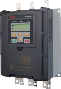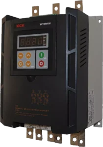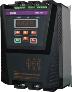
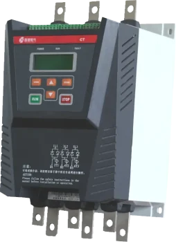
XICHI CT Series High Starting Torque Soft Starter, 18–1000 A / 7.5–530 kW
The XICHI CT series is a three-phase low-voltage soft starter built for heavy duty applications that need high starting torque on squirrel-cage induction motors. Power electronics, microprocessor control and modern control theory work together to give stepped frequency conversion starting, stepless voltage regulation, low starting current and large starting torque through thyristor control – so you reduce the starting current, reduce the distribution capacity you have to install, and cut the mechanical stress that shortens motor and gearbox life.
Twenty-two ratings cover 18 A to 1000 A and 7.5 kW to 530 kW at 380 V, with the same starter available for 690 V and 1140 V systems. A current transformer is built in and the bypass contactor is supplied externally: terminals B1, B2 and B3 drive your bypass contactor, and the model table below lists the recommended contactor for every rating, together with the cable or busbar size for the main circuit. Selection is made against your motor current, not against catalogue power alone – part of the industrial drives and soft starters range Brigoind supplies.
Key Specifications at a Glance
| Parameter | Value |
|---|---|
| VOLTAGE & PHASE | 3-phase, AC380V / 690V / 1140V ±15% |
| CURRENT | 18A–1000A (22 ratings) |
| CONTROL | Voltage Ramp / Torque Control / Staged Frequency Start; Soft Stop |
| POWER | 7.5–530 kW |
| OVERLOAD | Electronic Thermal Overload (trip class 10 / 15 / 20 / 25 / 30 / Off) |
| COMMUNICATION | Modbus RTU / RS485 (slave address 1–32) |
Nineteen protection functions are available, so the starter also acts as the motor protection relay for overload, overcurrent, underload, phase loss and imbalance faults – see protection functions and fault codes.
Key Features
Fourteen built-in load application parameters
Fourteen load types are built in, each with its own starting control curve, so the start is matched to the driven machine instead of being tuned by trial and error: pumps, fans, compressors, conveyors, crushers, mixers, hoisting machinery, ship propellers and more.
Four starting modes, five stop modes
Voltage ramp start, linear torque control start, square torque control start and stepped frequency conversion control start. Programmable kick-start torque and current limitation can be applied under each mode. Stopping is selectable as free stop, soft stop, pump stop, internal braking or external braking – pump stop removes water hammer, soft stop removes the surge of a direct stop.
High starting torque by staged frequency conversion
During starting the starter first accelerates at a quarter of the rated frequency, then jumps to the power frequency for the final run-up. The quarter-frequency stage uses the voltage ramp method while the power-frequency stage uses the torque control curve, which is what allows heavy and constant torque loads – crushers, mixers, loaded conveyors – to break away and accelerate with a smaller supply.
Dual parameter sets (M1 / M2)
Two complete sets of control parameters are stored, so one starter can run two motors of different ratings – useful for duty/standby pairs and for machines with a main and an auxiliary drive.
Analog signal control and output
A 4–20 mA or 0–20 mA analog input with adjustable upper and lower limits can start, stop and alarm through process signals (pressure, temperature, flow), and a 4–20 mA / 0–20 mA analog output retransmits data to the control system.
RS485 Modbus RTU communication
An isolated RS485 port with the Modbus standard protocol built in supports PC, PLC and SCADA control with slave addresses 1–32. Real-time data and every setting are readable over the bus – see the register map.
Anti-interference and fault memory
All external control signals are optoelectronically isolated with different noise levels selectable for harsh plants. Up to 15 faults are stored with their codes, which makes intermittent faults traceable.
Friendly LCD human-machine interface
An LCD screen with navigation-style keys and English or Chinese menus, so parameter setting, fault display and real-time monitoring are straightforward for on-site electricians.
Technical Specifications
| Item | Specification |
|---|---|
| Control power | AC110V–AC220V ±15%, 50/60 Hz |
| Mains voltage (three-phase) | AC380V, 690V, 1140V ±15% |
| Nominal current | 18A–1000A, 22 rated values in total |
| Applicable motor | Ordinary squirrel-cage asynchronous (induction) motor |
| Starting ramp modes | Voltage ramp start, linear torque control start, square torque control start, stepped frequency conversion control start |
| Stop modes | Free stop, soft stop, pump stop, internal braking, external braking |
| Logical input | Impedance 1.8 kΩ, power supply +24V |
| Start frequency | Frequent or infrequent start available, internally settable (starting interval parameter Q09) |
| Protection functions | 19 protections – over-voltage, under-voltage, three-phase voltage imbalance, overcurrent, overload, underload, overheating, phase loss, short circuit, three-phase current imbalance, phase sequence, leakage current, zero sequence, motor temperature (PTC), thyristor, starting timeout, frequent start, system abnormality and more |
| Protection level | IP00, IP20 |
| Cooling type | Natural cooling or forced air cooling |
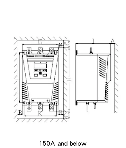
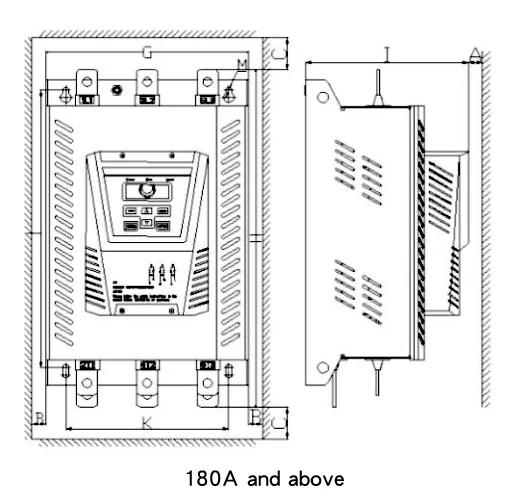
| Installation type | Wall mounted, vertical (up-in, down-out main circuit wiring) |
| Ambient temperature | −25 to +45 °C |
| Relative humidity | Less than 95% (at 20 °C ±5 °C), no condensation |
| Altitude | Derate above 2,000 m |
| Installation environment | Indoor, good ventilation; free of flammable, explosive or corrosive gas and conductive dust; vibration below 0.5 G |
| External control terminals | 23 terminals (X1 digital, X2 analog and RS485, X3 relay and control power) |
| Display / interface | LCD display with English and Chinese menus, keypad operation |
| Communication | RS485, Modbus RTU, slave address 1–32 |
| Applicable standard | GB/T 14048.6-2016, utilization category AC-53b |
Model Selection: 22 Ratings from 18 A to 1000 A
The table below is the standard 380 V selection table from the manufacturer. Choose the row whose rated current is above your motor full-load current, then add the listed bypass contactor. For 690 V and 1140 V systems the same current ratings apply and accessories are selected on the controller current.
| Motor power (kW) | Soft starter model | Rated current (A) | Bypass contactor model | Primary wire / busbar |
|---|---|---|---|---|
| 7.5 | CT-0018/3 | 18 | CJX4-25 | 4 mm² |
| 11 | CT-0024/3 | 24 | CJX4-32 | 6 mm² |
| 15 | CT-0030/3 | 30 | CJX4-32 | 10 mm² |
| 18.5 | CT-0039/3 | 39 | CJX4-40 | 10 mm² |
| 22 | CT-0045/3 | 45 | CJX4-50 | 16 mm² |
| 30 | CT-0060/3 | 60 | CJX4-63 | 25 mm² |
| 37 | CT-0076/3 | 76 | CJX4-80 | 35 mm² |
| 45 | CT-0090/3 | 90 | CJX4-95 | 35 mm² |
| 55 | CT-0110/3 | 110 | CJX4-115F | 35 mm² |
| 75 | CT-0150/3 | 150 | CJX4-150F | 50 mm² |
| 90 | CT-0180/3 | 180 | CJX4-185F | Copper busbar |
| 110 | CT-0218/3 | 218 | CJX4-225F | Copper busbar |
| 132 | CT-0260/3 | 260 | CJX4-265F | Copper busbar |
| 160 | CT-0320/3 | 320 | CJX4-330F | Copper busbar |
| 185 | CT-0370/3 | 370 | CJX4-400F | Copper busbar |
| 220 | CT-0440/3 | 440 | CJX4-500F | Copper busbar |
| 250 | CT-0500/3 | 500 | CJX4-500F | Copper busbar |
| 280 | CT-0560/3 | 560 | CJX4-630F | Copper busbar |
| 315 | CT-0630/3 | 630 | CJX4-630F | Copper busbar |
| 400 | CT-0780/3 | 780 | JWCJ20-800 | Copper busbar |
| 470 | CT-0920/3 | 920 | JWCJ20-1000 | Copper busbar |
| 530 | CT-1000/3 | 1000 | JWCJ20-1000 | Copper busbar |
How to read the model code: CT-xxxx/y – the four digits are the rated current in amperes and the digit after the slash is the voltage class, for example 3 = 380 V. So CT-0218/3 is a 218 A starter for a 380 V supply, and CT-1000/3 is the 1000 A, 530 kW end of the range.
Please note: the bypass contactor is not built into the CT series. Terminals B1, B2 and B3 provide the bypass output; a current transformer is included as standard. Copper cable of 4–50 mm² covers models from 18 A to 150 A, and copper busbar is used from 180 A upward (30 × 3 mm to 50 × 6 mm). Main circuit wiring is up-in and down-out, and the cable must be rated for the starter current.
Start, Stop and Protection Parameters
Every value below is settable from the keypad and readable over Modbus. M1 and M2 each hold a full set, so the parameter groups can be switched with the running motor.
Basic start/stop parameters (C parameters)
| Code | Parameter | Setting range / options | Factory value |
|---|---|---|---|
| C01 | Start method | 0. Voltage ramp control · 1. Linear torque control · 2. Squared torque control · 3. Staged frequency conversion starting control (heavy and constant torque loads) | 0 |
| C02 | Step (kick) method | 0. Voltage drop step · 1. Low-frequency step | 0 |
| C03 | Step voltage | 20–100% Ue | 20% |
| C04 | Step time | 0–2000 ms | 0 |
| C05 | Initial voltage | 20–100% Ue | 30% |
| C06 | Ramp time | 0–120 s (0 = system assigns 3 s) | 10 |
| C07 | Current-limiting multiple | 100–500% Ie (500% = no current limit) | 350% |
| C08 | Secondary start current-limiting start time | 0–60 s (disable at zero) | 0 |
| C09 | Secondary start current-limiting multiple | 100–500% Ie | 400% |
| C10 | Stop mode | 0. Free stop · 1. Soft stop (linear torque control) · 2. Pump stop (square torque control) · 3. Internal braking · 4. External braking | 0 |
| C11 | Soft-stop time | 0–120 s | 10 |
| C12 | Soft-stop initial voltage | 60–100% Ue | 80% |
| C13 | Soft-stop final voltage | 0–60% Ue | 20% |
| C14 | Braking time | 0–120 s (disable at zero) | 10 |
| C15 | Braking force | 10–100% | 30% |
| C16 | Inching force | 10–100% | 30% |
| C17 | Inching forward speed | 0. 15% rated speed · 1. 7% rated speed (low) | 0 |
| C18 | Inching reverse speed | 0. 20% rated speed · 1. 10% rated speed (low) | 0 |
| C19 | Motor rated current | 15–9999 A | set to motor nameplate |
Protection parameters (B parameters)
| Code | Parameter | Setting range / options | Factory value |
|---|---|---|---|
| B00 | Overload protection level | 10 / 15 / 20 / 25 / 30 / OFF (set to 6) | 20 |
| B01 | Current imbalance protection | 0–100% (100% = turned off) | 40% |
| B02 | Current imbalance protection delay | 0–250 s | 2 |
| B03 | Over-current protection | 100–500% Ie (100% = turned off) | 300% |
| B04 | Over-current protection delay | 0–250 s | 2 |
| B05 | Under-load protection | 0–99% Ie (0 = turned off) | 0 |
| B06 | Under-load protection delay | 0–250 s | 2 |
| B07 | Thyristor protection | 0. Disable · 1. Enable | 0 |
| B08 | Leakage lockout protection | 0. Disable · 1. Enable | 0 |
| B09 | Phase sequence protection | 0. Disable · 1. Enable | 0 |
| B10 | Zero sequence protection | 0. Disable · 1. Enable | 0 |
| B11 | Motor temperature protection | 0. Disable · 1. Enable | 0 |
| B12 | Starting time limit | 0–250 s | 60 |
| B13 | Inching time limit | 0–60 s | 60 |
The ramp time (C06) sets the rate at which the output voltage rises rather than the actual starting time; the real starting time also depends on the current limit and on the load. If ramp time is set to 0 the system assigns 3 seconds automatically. During the starting process only free stop is available; soft stop, pump stop and braking stop apply after the start is complete.
Built-in Load Presets for 14 Applications
Selecting the load type in C00 loads a starting curve matched to that machine. The reference values below are the manufacturer settings for each load type and are a good starting point before fine tuning on site.
| Type of load | Initial voltage (%) | Start ramp time (s) | Stop ramp time (s) | Current limit ILIM |
|---|---|---|---|---|
| Ship’s propeller | 20 | 10 | 0 | 2.5 |
| Centrifugal fan | 20 | 20 | 0 | 3.5 |
| Centrifugal pump | 20 | 6 | 6 | 3 |
| Reciprocating compressor | 20 | 15 | 0 | 3 |
| Lifting machinery | 30 | 15 | 6 | 3.5 |
| Mixer | 40 | 15 | 0 | 3.5 |
| Crusher | 30 | 15 | 6 | 3.5 |
| Screw compressor | 20 | 15 | 0 | 3.5 |
| Screw conveyor | 20 | 10 | 6 | 3.5 |
| No-load motor | 20 | 10 | 0 | 2.5 |
| Belt conveyor | 20 | 15 | 10 | 3.5 |
| Heat pump | 20 | 15 | 6 | 3 |
| Escalator | 20 | 10 | 0 | 3 |
| Air pump | 20 | 10 | 0 | 2.5 |
Terminals and Control Wiring
The CT starter has 23 external control terminals for remote control, system control and signal wiring.
Main circuit terminals
| Terminal | Name | Description |
|---|---|---|
| 1L1, 3L2, 5L3 | AC power input terminal | Connected to the three-phase AC supply |
| B1, B2, B3 | External bypass output terminal | Connected to the external bypass contactor |
| 2T1, 4T2, 6T3 | Soft start output terminal | Connected to the asynchronous motor |
Control circuit terminals
| Terminal | Name | Description |
|---|---|---|
| X1/1 | COM | COM |
| X1/2 | External control starting terminal | Start when X1/1 and X1/2 are short-circuited |
| X1/3 | External control stopping terminal | Stop when X1/1 and X1/2 are disconnected |
| X1/4 | Programmable digital port D1 | Function set by functional parameters Q04 and Q05 |
| X1/5 | Programmable digital port D2 | Function set by functional parameters Q04 and Q05 |
| X1/6 | Digital port D3 | Motor temperature detection (PTC) |
| X1/7 | Digital port D4 | Current leakage detection |
| X1/8 | COM | COM |
| X2/1 | Analog current input − | 0–60 mA analog input, set by functional parameter Q06 |
| X2/2 | Analog current input + | 0–60 mA analog input, set by functional parameter Q06 |
| X2/3 | Analog current output − | 0–20 mA analog output, set by functional parameter Q07 |
| X2/4 | Analog current output + | 0–20 mA analog output, set by functional parameter Q07 |
| X2/5 | 485 COM A | RS485 interface, Modbus communication protocol |
| X2/6 | 485 COM B | RS485 interface, Modbus communication protocol |
| X3/1, X3/2 | K1 failure relay output | K11–K12 close when the output is effective; contact capacity AC250V/5A, DC30V/5A |
| X3/3, X3/4 | K2 bypass relay output | K21–K22 close when the output is effective; contact capacity AC250V/5A, DC30V/5A |
| X3/5, X3/6 | K3 programmable relay output | K31–K32 close when the output is effective; contact capacity AC250V/5A, DC30V/5A |
| X3/7 | PE | To ground |
| X3/8, X3/9 | Control power | AC110–220V ±15%, 50/60 Hz |
The start and stop input is a passive node: when X1/1 and X1/2 are short-circuited the starter starts, when they are disconnected it stops. Keep the PE grounding wire as short as possible, bond it to the installation plate close to the starter and ground the plate as well. The control loop diagram is factory set for single-node control; the LED panel start key is inactive in that mode.
RS485 Modbus Communication
The CT soft starter uses an RS485 hardware interface and the Modbus RTU protocol for master-slave communication, so it can be integrated into a PC, PLC or upper-computer control system. Up to 32 slaves are addressed on one bus and every slave needs its own address.
- Interface: RS485, terminals X2/5 (485 COM A) and X2/6 (485 COM B)
- Transmission: asynchronous serial, half-duplex, RTU mode, 8-bit bytes transmitted as two hexadecimal characters (0–9, A–F) with CRC check
- Topology: single-master multi-slave, slave address range 1–32
- Framing: at least 3.5 bytes of silent interval start a new frame; a frame interrupted by more than 1.5 bytes is discarded
- Status word: the low byte reports the state – stop, edit, running (0x40), inching (0x60) or fault (0x80) – with sub-states such as starting delay, leakage detection, step, ramp, current limiting, soft start, brake countdown, pump stop and so on
Real-time measured data (read only)
| Name | Register | Type | Access |
|---|---|---|---|
| Working status of soft starter | 0000 | Uint | R |
| Current fault 1 | 0001 | Uint | R |
| Current fault 2 | 0002 | Uint | R |
| Current fault 3 | 0003 | Uint | R |
| Motor rated current | 0004 | Uint | R |
| Motor average current | 0005 | Uint | R |
| L1 phase current | 0006 | Uint | R |
| L2 phase current | 0007 | Uint | R |
| L3 phase current | 0008 | Uint | R |
| Analog input port value % | 0009 | Uint | R |
| Output voltage % | 0010 | Uint | R |
| L1–L2 line voltage | 0011 | Uint | R |
| L2–L3 line voltage | 0012 | Uint | R |
| L3–L1 line voltage | 0013 | Uint | R |
| Status of IO port | 0014 | Uint | R |
| Starting interval countdown | 0015 | Uint | R |
| Starting countdown time | 0016 | Uint | R |
M1 basic parameter registers (read / write)
| Name | Register | Type | Access |
|---|---|---|---|
| Selection of application parameters | 0020 | Uint | R/W |
| Start method | 0021 | Uint | R/W |
| Step method | 0022 | Uint | R/W |
| Step voltage | 0023 | Uint | R/W |
| Step time | 0024 | Uint | R/W |
| Initial voltage | 0025 | Uint | R/W |
| Ramp time | 0026 | Uint | R/W |
| Current-limiting multiple | 0027 | Uint | R/W |
| Secondary start current-limiting start time | 0028 | Uint | R/W |
| Secondary start current-limiting multiple | 0029 | Uint | R/W |
| Stop mode | 0030 | Uint | R/W |
| Soft-stop time | 0031 | Uint | R/W |
| Soft-stop initial voltage | 0032 | Uint | R/W |
| Soft-stop final voltage | 0033 | Uint | R/W |
| Braking time | 0034 | Uint | R/W |
| Braking force | 0035 | Uint | R/W |
| Inching force | 0036 | Uint | R/W |
| Inching forward speed | 0037 | Uint | R/W |
| Inching reverse speed | 0038 | Uint | R/W |
| Motor’s rated current | 0039 | Uint | R/W |
| Over-load protection level | 0050 | Uint | R/W |
| Current imbalance protection | 0051 | Uint | R/W |
| Current imbalance protection delay | 0052 | Uint | R/W |
| Over-current protection | 0053 | Uint | R/W |
| Over-current protection delay | 0054 | Uint | R/W |
| Under-load protection | 0055 | Uint | R/W |
| Under-load protection delay | 0056 | Uint | R/W |
| Thyristor protection | 0057 | Uint | R/W |
| Leakage lockout protection | 0058 | Uint | R/W |
| Phase sequence protection | 0059 | Uint | R/W |
| Zero sequence protection | 0060 | Uint | R/W |
| Motor temperature protection | 0061 | Uint | R/W |
| Starting time limit | 0062 | Uint | R/W |
Protection Functions and Fault Codes
The starter monitors current and load continuously and carries 19 protection functions. When a protection operates the yellow LED lights, the starter shuts down immediately and the fault code appears on the LCD, with up to 15 faults stored in memory. Each code has a defined cause and a defined clearing action, so a maintenance technician can act without the manual open on the bench.
| Code | Fault | Typical cause | What to check / do |
|---|---|---|---|
| 01 | Phase loss of main power | Phase loss during start or running | Check the three-phase power supply is reliable |
| 02 | Phase sequence error | Reverse phase sequence | Correct the phase sequence of the incoming supply, or set B09 to disable phase sequence detection |
| 03 | Loss of parameter | Parameter setting lost | Check functions and reset |
| 04 | Overload protection | Current stays too high for a period of time, overloading the motor | Remove the cause of overload; check the current-limiting multiple, the starting time, the overload level and the motor rated current |
| 05 | Operation overcurrent | Load suddenly increased or load fluctuation too large | Adjust the load operating conditions; check B03 settings are not too low |
| 06 | Underload protection | Motor operating current below the rated current | Find and correct the cause of underload; check settings against real operating conditions |
| 07 | Phase current imbalance | Three-phase current imbalance | Check the imbalance against B01; adjust the load running status |
| 08 | Over-voltage protection | Main circuit voltage too high | Check the incoming voltage; check parameter Q24 |
| 09 | Under-voltage protection | Main circuit voltage too low | Check the incoming voltage; check parameter Q26 |
| 10 | Phase voltage imbalanced | Three-phase supply voltage imbalanced | Check the three-phase voltage of the main circuit; check parameter Q23 |
| 11 | SCR abnormal | Thyristor fault | Check whether the thyristor is short-circuited |
| 12 | Leakage lockout | Insulation below the lockout threshold | Check the grounding insulation of the three-phase winding |
| 13 | Start timeout | Starting time too long | Check the current-limiting multiple is not too small; check the starting time limit B12 is not too low |
| 14 | Thyristor overheating | Internal heat sink overheating or poor ventilation of the cubicle | Check the fan works reliably; reduce the starting frequency; check the control supply voltage |
| 15 | Motor temperature | PTC thermistor inside the motor reports high temperature | Check the PTC loop is closed and wired; find the cause of overheating; wait until the motor has cooled |
| 16 | Frequent start | Starting too frequently | The starting frequency exceeds the set starting interval parameter Q09 |
| 17 | Frequency fault | Frequency out of range | Check and change the power frequency |
| 18 | Zero sequence protection | Zero sequence current detected | Check whether the three-phase leakage exceeds the design value |
| 19 | Inching timeout | Inching time too long | The inching time exceeds the set inching time limit B13 |
Current fault registers 0001, 0002 and 0003 report the active fault bits over Modbus, so the same codes can be read remotely instead of from the panel. By default thyristor, leakage lockout, phase sequence, zero sequence and motor temperature protection are disabled and must be enabled for the installation if the application needs them – in which case leakage lockout also requires the K3 relay output (parameter Q17) to be set to 7.
How to Select the Right CT Rating
- Read the motor nameplate full-load current (FLC), not just the kW. For a 380 V motor, pick the CT model whose rated current is next above the FLC from the model table; if the motor nameplate current is higher than the standard rating, go one size up.
- Check the duty. For heavy and constant torque loads – crushers, mixers, loaded belt conveyors, screw conveyors – allow one rating of margin, and use the staged frequency conversion start curve (C01 = 3) for the high starting torque.
- Add the bypass contactor from the same table, plus the matching cable or busbar. The bypass closes after the start is complete, which keeps losses and heat low during running.
- Set the protection. Enter the motor rated current (C19), the overload level (B00) and, if the plant needs it, the underload, imbalance, phase sequence and leakage protections.
- One starter, two motors? Use the dual M1/M2 parameter sets to store two complete motor configurations.
Applications that only need 7.5 kW to 280 kW or 7.5 kW to 630 kW with a built-in bypass may be better served by another XICHI series – see the industrial drives range, the Modbus RTU soft starter (CMC-MX, built-in bypass, 7.5–280 kW), the built-in bypass soft starter (CMC-LX, 7.5–630 kW) or the soft starter for pump, fan and compressor duty (CMC-HX, 7.5–710 kW). Send us the motor data and we will confirm the rating, the contactor and the wiring method for the project.
Applications
- Centrifugal, hydraulic, heat and air pumps
- Centrifugal and axial flow fans
- Reciprocating and screw air compressors
- Belt conveyors and screw conveyors
- Crushers and mixers
- Ship propellers and marine drives
- Lifting machinery and escalators
- Water treatment and pumping stations
- HVAC, refrigeration and heat exchange plants
- Cement, mining and metallurgy plants
- Chemical, petrochemical and oil and gas installations
- Power plants and boiler feed systems
- Food, beverage and textile machinery
- Steel and metal processing lines
- Machines fed from 690 V or 1140 V distribution
Because the CT starter is selected on current and on load torque, the same model family covers pump stations, crusher lines and heavy conveyors. Some of the installations where Brigoind soft starters have been supplied are listed in our soft starter projects.
FAQ
Does the CT soft starter have a built-in bypass?
No. The CT series has a built-in current transformer but the bypass contactor is external. Terminals B1, B2 and B3 drive the bypass contactor and the closing signal is provided by the K2 bypass relay output. The model table lists the recommended contactor for each rating. If you need the bypass built into the starter, look at the CMC-MX or CMC-LX series.
What motor data do I need to select a CT model?
The motor nameplate full-load current, the supply voltage and frequency, the load type and the starting conditions. Selection is by current, so a 90 kW motor with a high nameplate current may need the next rating up. Send us the nameplate data and we will confirm the model, the bypass contactor and the wiring method.
Which voltages does the CT series support?
The CMC-CT series is designed for three-phase AC380V, 690V and 1140V ±15%, with a separate control supply of AC110V–AC220V ±15%, 50/60 Hz. The series table in the manual is given for 380 V as an example; for 690 V and 1140 V the same rated currents are used and accessories are selected on the controller current.
How do I set the starter for a pump, a fan or a crusher?
Select the load type in parameter C00, which loads the matched starting curve, then fine tune the initial voltage, ramp time, current limit and stop mode. The preset table gives reference values for fourteen common load types, including centrifugal pumps and fans, reciprocating and screw compressors, crushers, mixers, belt and screw conveyors and ship propellers.
Does it support Modbus and can I read the data remotely?
Yes. The starter has an RS485 port using the Modbus RTU protocol with slave addresses 1–32. Real-time values such as phase currents, line voltages, output voltage, analog input value and working status are readable, and all start, stop and protection parameters can be read and written. The register numbers are listed in this page.
What happens when a fault occurs?
The yellow LED lights, the starter trips immediately and the fault code (01–19) appears on the LCD. Up to 15 faults are stored for later review, and the active fault is also reported in Modbus registers 0001–0003. Each code has a defined cause and clearing action, listed in the fault code table above.
Can the starter run two different motors?
Yes. Two complete parameter sets (M1 and M2) are stored, each with its own application, basic and protection settings, so one starter can drive two motors of different power ratings – for example a duty and a standby pump of different sizes.
How is the ramp time related to the actual starting time?
Ramp time (C06) is the rate at which the output voltage rises, not a timer for the starting sequence. The actual starting time also depends on the current-limiting multiple and on the load: a lighter load and a lower current limit shorten the run-up. If ramp time is set to 0, the system assigns 3 seconds automatically.
What protection functions are built in?
Nineteen, covering overload, overcurrent, underload, phase loss, phase sequence, over-voltage, under-voltage, three-phase voltage and current imbalance, SCR abnormal and overheating, leakage lockout, zero sequence, motor temperature (PTC), starting and inching timeout, frequent start, frequency fault and system abnormality. Some are disabled at the factory and must be enabled for the installation.
What are the ambient limits and the enclosure rating?
IP00 or IP20, wall mounted, natural or forced air cooling. Ambient temperature −25 to +45 °C, relative humidity below 95% at 20 °C ±5 °C, indoor installation with good ventilation and vibration below 0.5 G. Above 2,000 m altitude the starter must be derated. For dusty or humid plants, install it in a suitable enclosure and follow the maintenance procedure in the manual.
Request a Quotation
Send us the motor nameplate data (voltage, frequency, full-load current, power), the load type and the starting conditions, and we will confirm the CT model, the bypass contactor and the main circuit accessories. Mixing CT starters with other XICHI soft starter series in one project? Ask us to quote them together so the parameters and spare parts stay consistent.
As a long-term XICHI distributor, the selection sits close to the way the machine is actually started. Request a CT soft starter quotation or learn more about Brigoind.