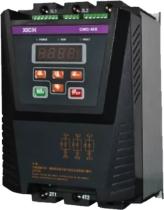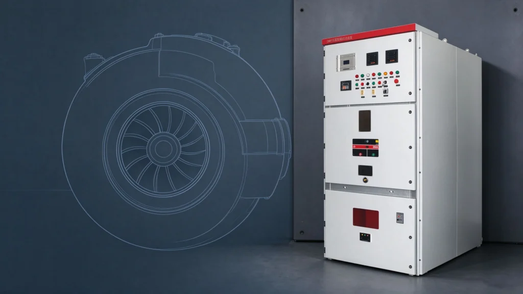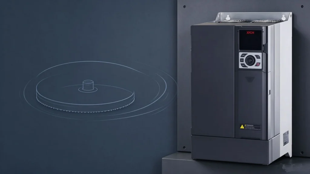
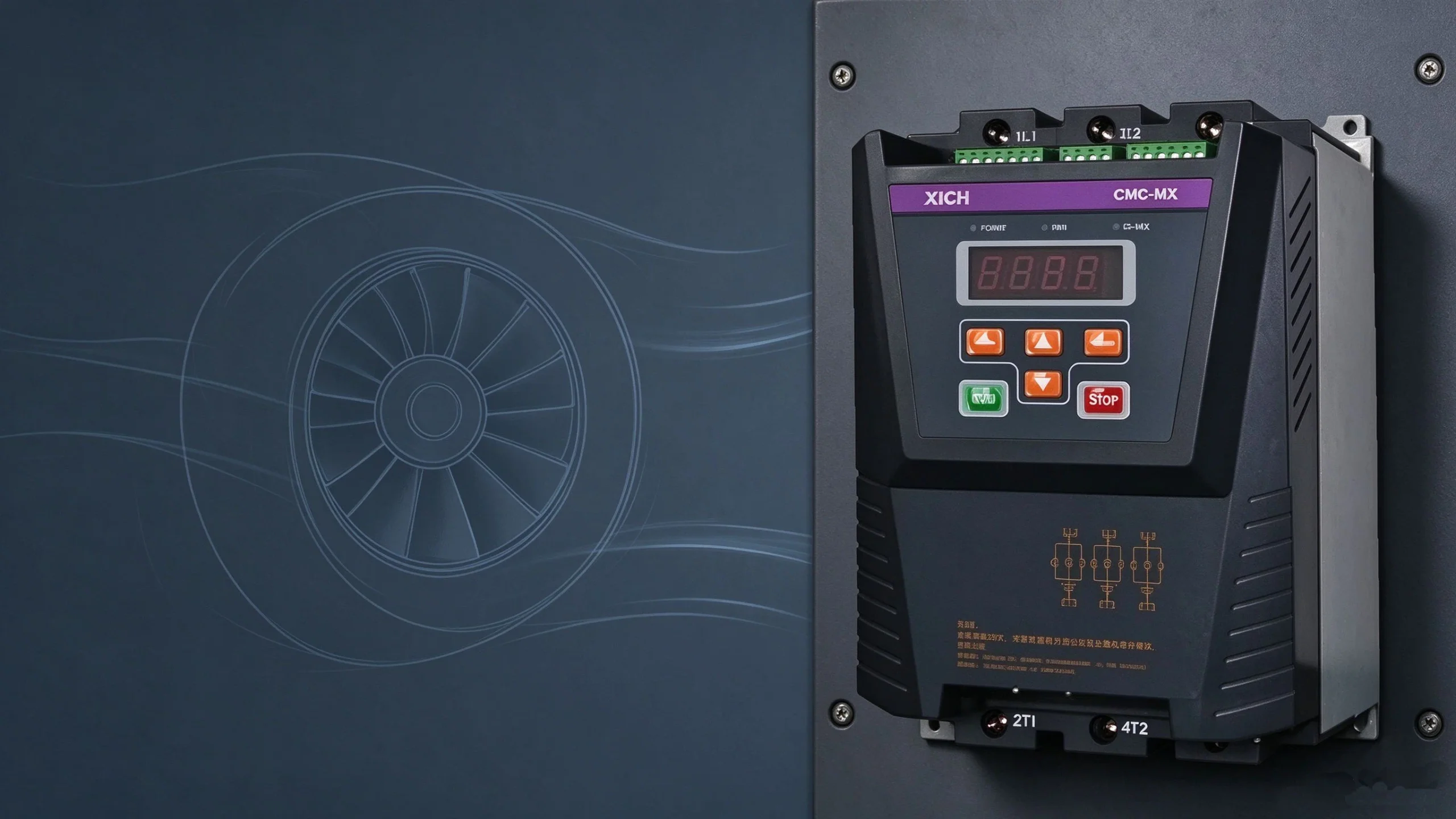
Low-voltage auxiliary systems of a fan unit — the barring (turning) motor, lube oil pump and hydraulic oil pump — directly affect fan performance and reliability. A CMC-MX series built-in bypass soft starter (380 V, 7.5–280 kW) combines power electronics, a microprocessor and modern control theory with dedicated motor protection and software. It reshapes the starting characteristic, lowers starting current, reduces grid impact and supports network communication for intelligent control. In function, load adaptability, maintenance and reliability it goes beyond traditional starters such as star-delta, autotransformer and magnetic-control reduced-voltage units, making solid-state soft starting the natural replacement.
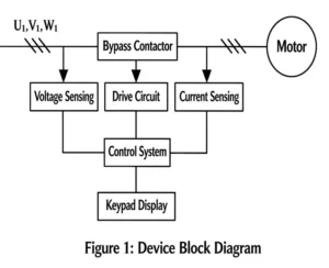
1. Unit Composition (Figure 1)
The soft starter uses a single-chip microcontroller for logic control and typically consists of voltage detection, current detection, bypass contactor, drive circuit, control system, and keypad/display.
[Figure 1 — Unit composition block diagram: supply → voltage detection / current detection → control system → drive circuit → bypass contactor → motor; keypad display connected to the control system.]
2. Selecting the Start and Stop Modes
Selection depends mainly on the required start method and stop method.
Start modes
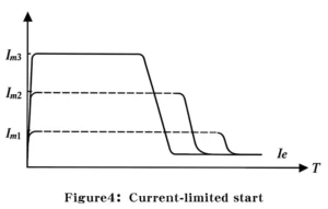
- Current-limited start: caps starting current; for light-load starts and applications with a strict starting-current limit.
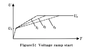
- Voltage ramp start: voltage rises linearly from low to high; for heavy-load starts where smoothness matters more than a tight current limit.
- Kick start (pulse start): applies a short, fixed higher voltage at the beginning to overcome static breakaway torque; for heavy loads, though the kick gives a brief grid impulse.
- Torque control start: starting torque ramps linearly up; suited to heavy loads.
- Voltage control start: holds the starting voltage drop steady while developing starting torque; for light loads.
Stop modes
- Deceleration (soft) stop: for pumps; effectively reduces pressure surge and water hammer.
- Free stop: coast to a stop.
- Braking stop: for high-inertia loads.
3. Benefits
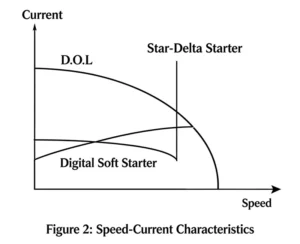
On the grid side (Figure 2): avoids a large voltage dip and grid impact, controls starting current, eliminates the peak inrush current, and keeps wiring simple.
[Figure 2 — Speed vs current: DOL and star-delta curves versus the digital soft starter curve.]
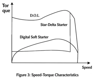
On the mechanical side (Figure 3): reduces stress on gearbox, belts and bearings; lowers water-hammer effect; cuts maintenance cost and shortens downtime.
[Figure 3 — Speed vs torque: DOL and star-delta torque steps versus the smooth digital soft starter torque curve.]
Other benefits: start method and parameters adjustable to the load; high-performance microprocessor and control software; high reliability; compact size; easy installation; multiple protections (overcurrent, overload, phase loss, overheat); intuitive keypad for setting/modifying start-stop parameters; network communication with the control computer; settable output power to match the load.
4. Soft Starter vs Magnetic Reduced-Voltage and Autotransformer Starters
Aspect | Solid-state soft starter | Magnetic reduced-voltage | Autotransformer |
Starting characteristic | Soft, adjustable to requirement | Hard, fixed | Hard, fixed |
Starting current | Adjustable | Not adjustable | Not adjustable |
Initial voltage | Adjustable across 0–380 V | Fixed | Fixed |
Grid impact | Near zero | About 4–7× rated current, large impact | About 4–7× rated current, large impact |
Torque | Smooth, no shock torque | One shock torque, then smooth rise | Torque steps up, usually two shock torques |
Start modes | 5 selectable modes | Constant-current soft region only | Stepped constant-voltage |
Size / weight | Light and compact | Heavier and larger | Heavy, smaller footprint |
Control | High-performance single-chip logic | Relay + electronic components | Relay control |
5. Application in the Fan Auxiliary System
The soft starter removes the sudden voltage/current step of traditional reduced-voltage starts — such as low bus voltage and excessive starting current that disturb other loads on the bus — from the root.
Barring motor (15 kW, 380 V AC, 32 A rated current). Before unit startup the barring motor turns the fan shaft at very low speed to form an oil film on the shaft and reduce static resistance. It was previously started direct-on-line; the inrush shocked the gear coupled to the shaft and even caused damage. Because the barring motor must overcome a large breakaway torque at the instant of start, a kick-start mode soft starter was adopted, with excellent results.
Lube oil pump and hydraulic oil pump. Normally two pumps run duty/standby, mutually backup; when oil pressure drops, the standby pump must build pressure in the shortest time while respecting grid limits. A voltage control start mode was selected.
Bypass vs non-bypass wiring (Figures 6–7). Two wiring methods exist: with bypass and without bypass. In the bypass circuit, after startup completes the unit is bypassed and de-energized, which eases maintenance and inspection, so the bypass wiring was chosen.
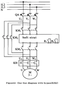
[Figure 6 — One-line diagram with bypass: QA breaker, KM1 run contactor, soft starter block, KM2 bypass contactor, KH thermal relay, motor M.]
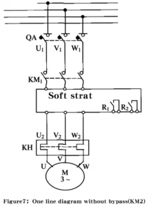
[Figure 7 — One-line diagram without bypass.]
Operating sequence: close the three-phase breaker QA and run contactor KM1; the soft starter powers up, self-checks internal components, and its internal relay R outputs a start-permit signal to the control circuit; the unit starts the motor; at rated speed the internal relay outputs a start-complete command to bypass contactor KM2; KM2 closes and takes the starter offline, ending startup.
Field reference: for a real fan installation outcome, see the case study of a CMC-MX built-in bypass soft starter on process fans at a Zhejiang environmental plant — 350% Ie current limit, 15 s ramp and 40% initial voltage.