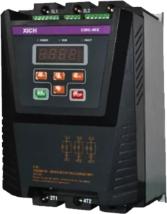
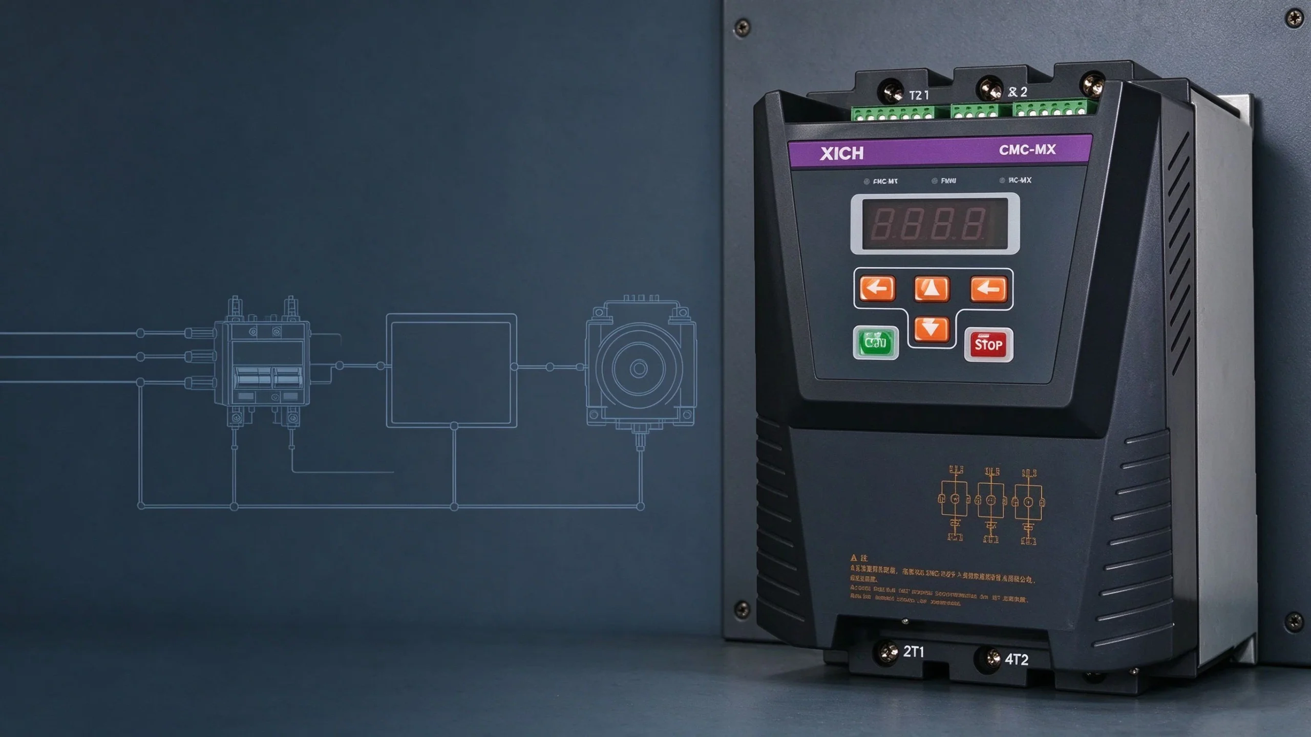
Wiring a built-in bypass soft starter correctly on the first visit saves panel rewiring, prevents motor and SCR damage, and keeps commissioning time short. This guide walks through the three connection layouts most panel builders and maintenance engineers meet on the CMC-MX series built-in bypass soft starter (380 V, 7.5–280 kW): the standard inline basic wiring, the inside-delta (six-wire) connection, and a complete typical application circuit with start/stop control and status indication. Because the bypass contactor is integrated inside the enclosure, no external bypass contactor is required, which cuts wiring points and frees panel space.
1. Basic Wiring Schematic (Inline / Standard Circuit)
Connect the three-phase supply to the line terminals 1L1, 3L2, 5L3, and connect the motor to the output terminals 2T1, 4T2, 6T3.
- No external bypass contactor needed: the internal bypass contactor closes once the motor reaches full speed, so the thyristors carry current only during the ramp-up and ramp-down phases, reducing heat buildup and continuous conduction losses.
- Phase sequence detection: enable or disable phase sequence (phase rotation) checking through a parameter setting; switch it on only where the installation requires a rotation check.
- Signal terminals available: analog output (+/−), digital inputs COM / RUN / STOP / DI, GND, RS485+ / RS485− communication, fault relay output (RL), programmable relay K2, and the L / N control supply fed through fuse FU.
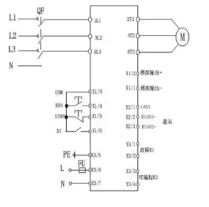
Figure 1. Basic inline wiring schematic: power circuit, control terminals, RS485 communication, fault relay and programmable K2 output.
2. Inside-Delta (Six-Wire) Connection Diagram
If the installation uses an inside-delta configuration, follow the diagram exactly; an incorrect winding connection can damage the motor or the soft starter.
Before every start, the CMC-MX checks the motor winding configuration. If the wiring does not match the selected mode, the starter trips a wiring-error (connection mismatch) fault instead of energizing the SCRs — do not bypass this protection to force a start.
In an inside-delta circuit each SCR carries winding phase current (about 1/√3 of line current), which allows a smaller frame size for the same motor — but this benefit applies only when all six motor winding leads are accessible and the diagram is followed precisely.
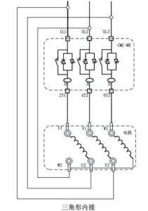
Figure 2. Inside-delta (six-wire) connection: SCR branches connected into the motor delta winding; wiring mismatch triggers a wiring-error fault before startup.
3. Typical Application Wiring Diagram
Main circuit: supply → QF molded-case breaker → CMC-MX → motor M; voltmeter PV and ammeter PA monitor the circuit.
Control circuit (AC 220 V): QF1 micro-breaker feeds the control supply. SB1 (normally open) starts, SB2 (normally closed) stops, through auxiliary relay KA1 / KA2. Pilot lights indicate status: HL1 fault, HL2 running, HL3 stopped.
Two control modes are shown in the diagram:
- Single-node control (2-wire latching): a maintained contact between COM and RUN starts the unit; opening the contact stops it. Under this wiring the local LED panel START key is disabled.
- Dual-node control (3-wire momentary): a momentary NO start pushbutton together with an NC stop pushbutton wired across COM, RUN and STOP — the standard maintained-run control used on most MCC panels.
The control circuit follows the factory relay-output setting. If you modify the relay output mode in parameters, adjust the control wiring to match.
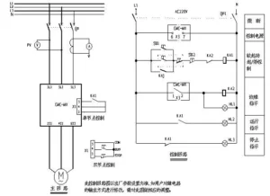
Figure 3. Typical application: main circuit with breaker and metering, AC 220 V control circuit with start/stop pushbuttons, KA1/KA2 and fault/run/stop indication lamps.
Installation Notes
- Single-node control behavior: closing the contact starts the starter and opening it stops it; LED panel start operation is invalid under this wiring. The start/stop signal on terminals 3, 4, 5 is a passive (dry, voltage-free) contact — supply your own contact, never apply voltage to these terminals.
- Mounting-plate functional ground: keep this ground conductor as short as possible. Land it on the mounting plate at the point closest to the starter, and ground the mounting plate itself. Although marked PE on the unit, this connection acts as a functional ground (EMC / signal reference) rather than the protective earth conductor; route the actual protective earth path separately in accordance with local safety codes (e.g., IEC 60204-1).
Field reference: for a real commissioning example, see the case study of a CMC-MX built-in bypass soft starter on process fans at a Zhejiang environmental plant — 350% Ie current limit, 15 s ramp and 40% initial voltage.